Unit-1
Introduction
Software engineering is a framework of building software, it’s essential to build quality and cost effective software. It’s defined as disciplined, systematic and quantifiable approach for the development, operation and maintenance of software.
Characteristics of Software
- Developed not manufactured in classic sense
- Doesn’t wear out but becomes unusable
- Custom build rather than assembling parts
Changing Nature of Software
The various categories of software are:
- System Software
- Application Software
- Web-Application
- Artificial Intelligence
- Embedded Software
- Product-line Software
- Engineering and Scientific Software
Legacy Software
Software that is build decades ago is called legacy software. The quality of legacy software is poor, inextensible, no documentation and tests cases and results are not achieved.
Legacy software should be updated for the following reasons:
- It should get adapted to new computing technology
- It should be enhanced to implement new business requirements
- It should be extensible with modern systems and databases
Myths of Software
Myths are widely held but false beliefs and views which propagate misinformation and confusion
Software myths have three categories:
- Management Myths
- Customer Myths
- Practitioner’s Myths
Management Myths
- Current software methods are enough for building software.
- Having latest equipment means having latest tools.
- Adding more programmers to team increases it’s efficiency.
- Outsource the work we can’t do.
Customer Myths
- An objective is enough to build software and details don’t matter.
- Software is flexible and easily modifiable.
Practitioner’s Myths
- Once the code is written, the job is done.
- Can’t test the quality of code before running it.
- Only way of delivering product is final product.
- Software engineering creates more work and documentation which slows down development.
Software Engineering - A Layered Technology
To develop software we need to go from one layer to another, the layers are:
- A quality of focus
- Process
- Methods
- Tools
Method: It has answers to all the “how-to-do” questions during software development
Tools: Provide semi-automatic and automatic support to methods
Process
- It’s the foundation of software engineering
- It binds all the layered technology which enables software development on or before the deadline
- It defines a framework for effective development
Process Framework
It defines a small set of activities that are applicable for all software projects and also include a set of umbrella activities that are applicable for all software processes. Process framework is a collection of tasks. Process framework includes:
- Tasks
- Actions
- Activities
Tasks: Focuses an a small specific objective
Actions: Group of tasks that produce a major work product
Activities: Group of tasks and actions for a major objective
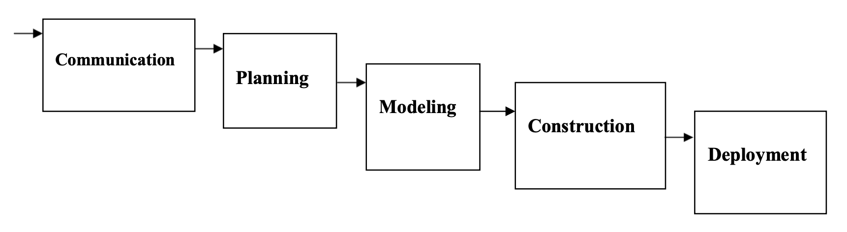
Process Framework Activities
- Communication
- Planning
- Modeling
- Construction
- Development
Umbrella Activities
- Formal Technical Reviews
- Software Configuration Management
- Risk Management
- Software Quality assurance
- Measurement
Capability Maturity Model Integration (CMMI)
It is developed by SEI (software engineering institute). It assesses the process followed by an organization and rate the process with different levels. A set of software engineering capabilities are required has you reach different levels of process capability and maturity.
CMMI can be represented in two ways:
- Continuous Model
- Staged Model
Continuous Representation
Lets the organization decide specific improvements that suits their business requirements and objectives and minimize risk. Levels are called Capability levels. Describes a process in 2 dimensions. Each process area is assessed against specific goals and is rated according to capability levels
Staged Representation
This model is used when you have no clue about how to improve the process for quality software. Levels are called Maturity Levels. It gives suggestions of what things other organizations have found helpful to work with.
CMMI Levels
- Initial
- Repeatable
- Defined
- Managed
- Optimizing
Process Pattern
A process patten describes a process related problem faced during software engineering work, identifies the problem and suggests proven solutions.
It compromises of the following:
- Process Template
- Initial context
- Problem
- Solution
- Resulting Context
- Related patterns
Process Assessment: Keeps check on the current software with the intention of improving it.
Process Models
Waterfall Model (Classic Life Cycle)
- Used when all requirements are well understood in the beginning
- A sequential and systematic approach
Problems
- Rarely used in real life development since projects are always iterative
- Working model is not available until the end of project
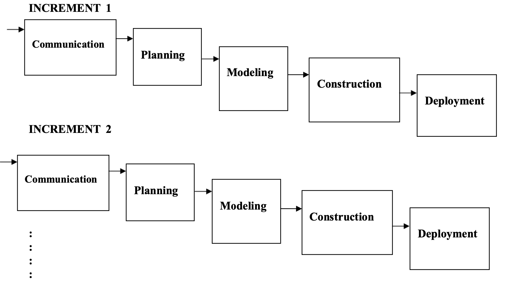
Incremental Model
- Linear sequential model is not suitable for iterative projects, here incremental model is used
- Used when initial requirements are reasonably known and compelled to provide limited functionality quickly
- Functionality expanded further in later releases, software is developed in increments
Rapid Application Model (RAD)
- It’s an incremental model having short development cycle
- Creates a fully functional system within a short span of around 60 to 90 days
It consists the following phases:
- Business modeling
- Data modeling
- Process modeling
- Application genration
- Testing and Turnover
Evolutionary Model
- Software evolves over a period of time
- Business requirements often change during the process making the path unrealistic, evolutionary models are iterative.
Types of evolutionary models:
- Prototype Model
- Spring Model
- Concurrent Model
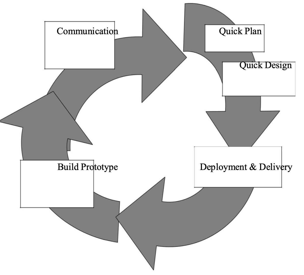
Prototype Model
- Mock up of a software
- Used when customer defines a set of objectives but does not identify input, output or processing requirements
Communication→(Quick Plan ⇒Quick Design )→ Construction of Prototype → Deployment
Spring Model
An evolutionary model which combines the features of Classic Life Cycle model and iterative nature of Prototype model.
It has four stages:
Planning of Objectives → Risk Analysis → Development → Review
Unified Model
- It’s an architecture-centric, use-case driven, iterative and incremental development process.
- Resulted in UML (Unified Modeling Language), a framework for Object-Oriented software engineering.
Phases:
- Inception Phase
- Elaboration Phase
- Construction Phase
- Transition Phase
- Production Phase
Unit-2
Software Requirements
IEEE Definition
- A condition or capability needed by a user to solve a problem or achieve an objective
- A condition or capability that must be met or possessed by a system or a system component to satisfy the contract
System Requirements
Encompasses both the Users view of the requirement and developers view
User’s Requirement: Statement in a natural language plus diagrams, describing the services that the system is expected to provide.
System’s Requirement: Describe the system’s function, services and operational condition
System Functional Requirements
- Statement of services that the system should provide
- Describes the behavior in certain situations
- Defines the system reaction to particular inputs
System Non-Functional Requirements
- Constraints on the services offered by the system
- Include timing constraints and development process
- Apply to system as whole
Domain Requirements
- Requirements relate to specific application of system
- Reflect characteristics and constraints of that system
Functional Requirements
- It describes functionality or system services
- It depends on the type of software, expected users and type of system where the software is used.
- Functional User Requirements may be high level statements of what the system should do
- Functional System Requirements should describe the system services in detail
Non Functional Requirements
- Defines system properties and constraints ex: reliability and response time
- These requirements are more critical than functional requirements and if not met the system is useless
Types:
- Product Requirements
- Efficiency
- Reliability
- Usability
- Portability
- Organization Requirements
- Delivery
- Implementation
- Standards
- External Requirements
- Interoperability
- Ethical
- Legislative
User Requirements
- Should describe functional and non-functional requirements so that a non technical person would understand them.
- User requirements are defined using natural languages, tables and diagrams
Interface Specification
- All the software system must operate with existing systems that are already implemented and in use.
- These specifications should be early in the process and included in the requirements document
Types:
- Procedural Interfaces
- Data Structures
- Representation of data
Procedural Interface: Where existing programs offer a range of services that are accessed by calling interface procedures. It’s used for calling the existing program by the new program. These interfaces are called Application Program Interface(API)
Data Structures: that are passed from one sub-system to another. Graphical data is an example.
Data Representations: that have been established for an existing sub-system. These interfaces are most common in embedded, real time system.
Software Requirement Document
The requirement document is the official statement of what is required of the system developers. Should include both the definition of user requirement and specifications of system requirement.
Six requirements that document should satisfy:
- Specify only external system behavior
- Specify constraints on the implementation
- Be easy to change
- Serve as reference tool for system maintainers
- Record forethought about the life cycle of the system
- Characterize acceptable responses to undesirable events.
Requirement Engineering Process
To create and maintain a requirement document, the whole process includes four sub-processes:
- Feasibility Study
- Elicitation and Analysis
- Specification
- Validation
Feasibility Study: Concerned with assessing whether the system is useful to the business
Elicitation and Analysis: Discovering requirements
Specification: Converting the requirements into a standard form
Validation: Checking the requirements actually define the system that user wants
System Models
Used in analysis process to develop understanding of the existing system or new system. It excludes details. It’s an abstraction of the system.
Types:
- Context Model
- Behavioral Model
- Data Model
- Object Model
- Structured Model
Context Model
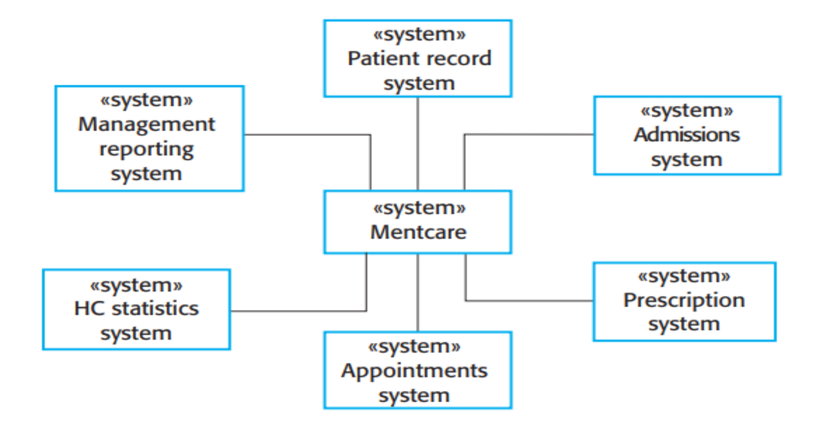
Context models are used to illustrate the operational context of a system, they show what lies outside the system boundaries. Architectural models show the system and it’s relationship with other systems.
Behavioral Model
These models are models of the dynamic behavior of system as it is executing. They show what happens or what is supposed to happen when a system responds to a stimulus from it’s environment.
Types:
- Data-driven modeling
- State machine models
Data-driven Model: Concentrate on the flow of data and functional transformation on that data. Show the processing of data and its flow through a sequence of processing steps.
State Machine Models: Describe how a system responds to internal or external events. Shows system states and events that cause transition from one state to another.
Data Model
Used to describe the logical structure of data processed by the system. An entity-relation- attribute model sets out the entities in the system, the relationships between these entities and the entity attributes. Widely used in database design.
Object Model
Used to describe the logical structure of data processed by the system. An entity-relation- attribute model sets out the entities in the system, the relationships between these entities and the entity attributes. Widely used in database design.
Unit-3
Unified Approach to Modeling
UML (Unified Modeling language), it’s primary goal is to establish a standard way to visualize how a system has been constructed. It’s a pictorial language used to make software blue prints.
UML is standard language for:
- Visualizing
- Specifying
- Construction
- Documenting
Visualizing: UML allows for the creation of visual models and diagrams that help stakeholders understand and visualize aspects of system
Specifying: UML provides a means to specify and define the characteristics and requirements of a system.
Construction: It helps in designing the architecture and components of a system.
Documentation: UML is extensively used for documentation.
Building blocks of UML
- Things
- Relationships
- Diagrams
Structural and Behavioral Diagrams
UML has nine diagrams
- Structural Diagrams:
- Class Diagram
- Object Diagram
- Component Diagram
- Deployment Diagram
- Behavioral Diagrams:
- Usecase Diagram
- Sequence Diagram
- Collaboration Diagram
- State Diagram
- Activity Diagram
Structural Diagram (Static Modeling)
| Type | Description | Example |
|---|---|---|
| Class Diagram | Represents static class structure and relationships | Modeling Library with classes like Book and Author |
| Object Diagram | Shows instances and their relationship at a specific movement | Displaying specific book and member objects |
| Component Diagram | Depicts physical or logical system components and their connections | Illustrating components like web servers and databases |
| Deployment Diagram | Displays physical deployment of components on nodes and servers | Presenting how servers are deployed |
Behavioral Diagram (Dynamic Modeling)
| Type | Description | Example |
|---|---|---|
| Use case Diagram | Defines and actors and their interactions with system through use cases | Modeling how a customer interacts with ATM to withdraw cash |
| Activity Diagram | Depicts Workflow, processes and actions in a system. | Illustrating the steps involved in processing an online order |
| State Diagram | Represents behavior of an object or sytem. | Modeling states of transitions of a Traffic Signal system |
| Sequence Diagram | Displays interactions with objects over time through messages | Messages b/w user and database during login process |
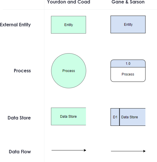
Data Flow Diagrams (DFD)
A data flow diagram graphically describes business processes and the flow of information that passes among them. It also describes inputs and outputs of a process and where the data will be stored.
Elements of DFD
- Entities
- Process
- Data Storage
- Data flow
Levels of DFD
- Level 0
- Level 1
- Level 2
Types of DFD
- Logical DFD
- Physical DFD
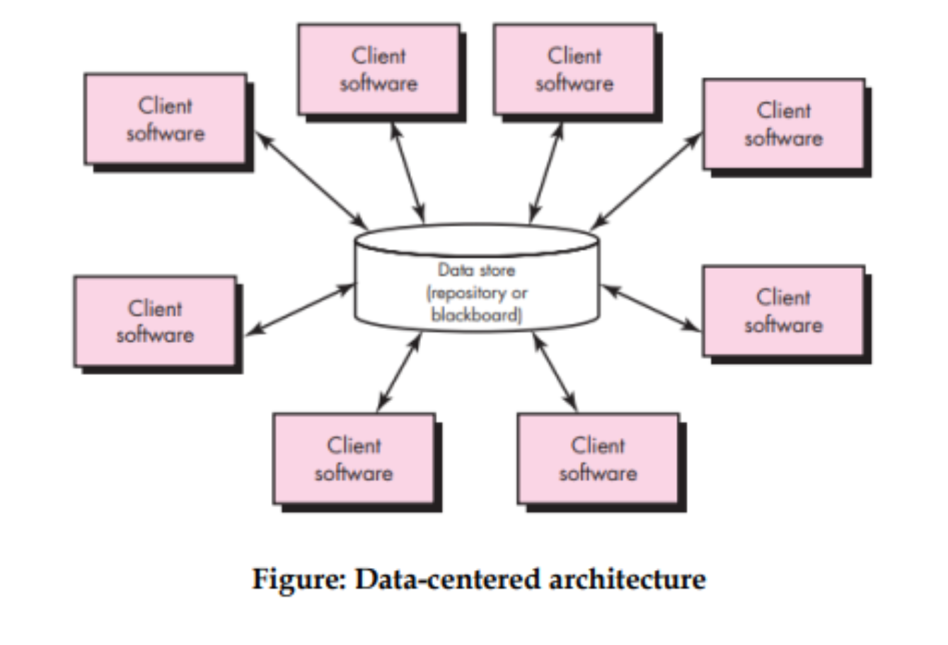
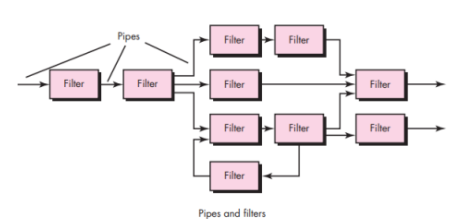
Architecture Styles
- Data-centered architectures
- Data-flow architectures
- Call and return architectures
- Object-oriented architectures
- Layered architectures
Data centered architecture
Data flow Architecture
Call and Return
Layered Architecture
Assessing Alternative Architecture Designs
An Architecture Trade-off Analysis Method (ATAM)
The design analysis activities which are executed iteratively that are as follows:
- Collect framework
- Elicit requirements, constraints, and environment description
- Describe the architectural styles/patterns that have been chosen to address the scenarios and requirements
- Evaluate quality attributes by considering each attribute in isolation
- Identify the sensitivity of quality attributes to various architectural attributes for a specific architectural style.
Unit-4
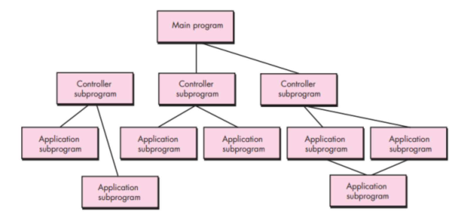
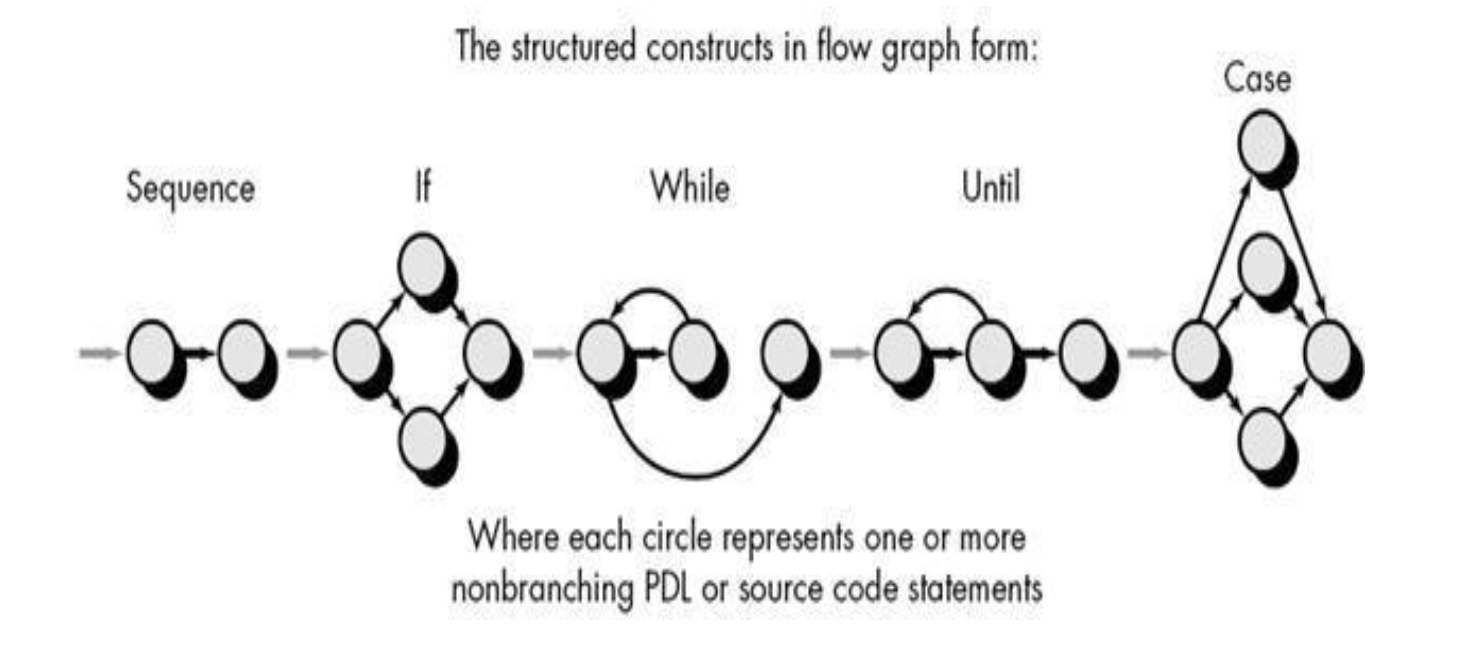
Structured Coding Techniques
In structured programming, we sub-divide the whole program into small modules so that the program becomes easy to understand. The purpose of structured programming is to linearize control flow through a computer program.This enhances the readability, testability, and modifiability of the program.
Rules:
- Code Block
- Sequence
- Alternation
- Iteration
- Nested Structures
Testing Strategies
- Unit Testing
- Integration Testing
- Validation Testing
- System Testing
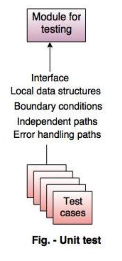
Unit Testing
The module interface is tested to ensure proper information flows (into and out). Local data structures are examined to ensure temporary data store during execution. All independent paths are exercised to ensure that all statements in a module have been executed at least once. Boundary conditions are tested to ensure that the module operates properly at boundaries. Software often fails at its boundaries. All error-handling paths are tested.
Integration Testing
In this the focus is on design and construction of the software architecture. It addresses the issues associated with problems of verification and program construction by testing inputs and outputs.
Types:
- Non Increment Integration Testing
- Increment Integration Testing
- Top-down Integration
- Bottom-up Integration
- Sandwich Integration
Validation Testing
Through Validation testing requirements are validated against s/w constructed. These are high-order tests where validation criteria must be evaluated to assure that s/w meets all functional, behavioural and performance requirements.
System Testing
In system testing, s/w and other system elements are tested as a whole. This is the last high-order testing step which falls in the context of computer system engineering. Software is combined with other system elements like H/W, People, Database and the overall functioning is checked by conducting a series of tests.
Types:
- Recovery Testing
- Security Testing
- Stress Testing
- Perfomance Testing
Regression Testing
Regression testing is the re-execution of some subset of tests that have already been conducted to ensure that changes have not propagated unintended side effects.
The regression test suite contains three different classes of test cases:
- A representative sample of tests that will exercise all software functions.
- Additional tests that focus on software functions that are likely to be affected by the change.
- Tests that focus on the software components that have been changed. As integration testing proceeds, the number of regression tests can grow quite large.
Testing Tactics
The goal of testing is to find errors and a good test is one that has a high probability of finding an error.
Types:
- Black Box Testing
- White Box Testing
Black Box Testing
This is also called behavioral testing and focuses on the functional requirements of software. It fully exercises all the functional requirements for a program and finds incorrect or missing functions, interface errors, database errors etc. This is performed in the later stages in the testing process.
Types:
- Graph Based Testing
- Equivalence Partitioning
- Boundary Value Analysis
- Orthogonal Array Testing
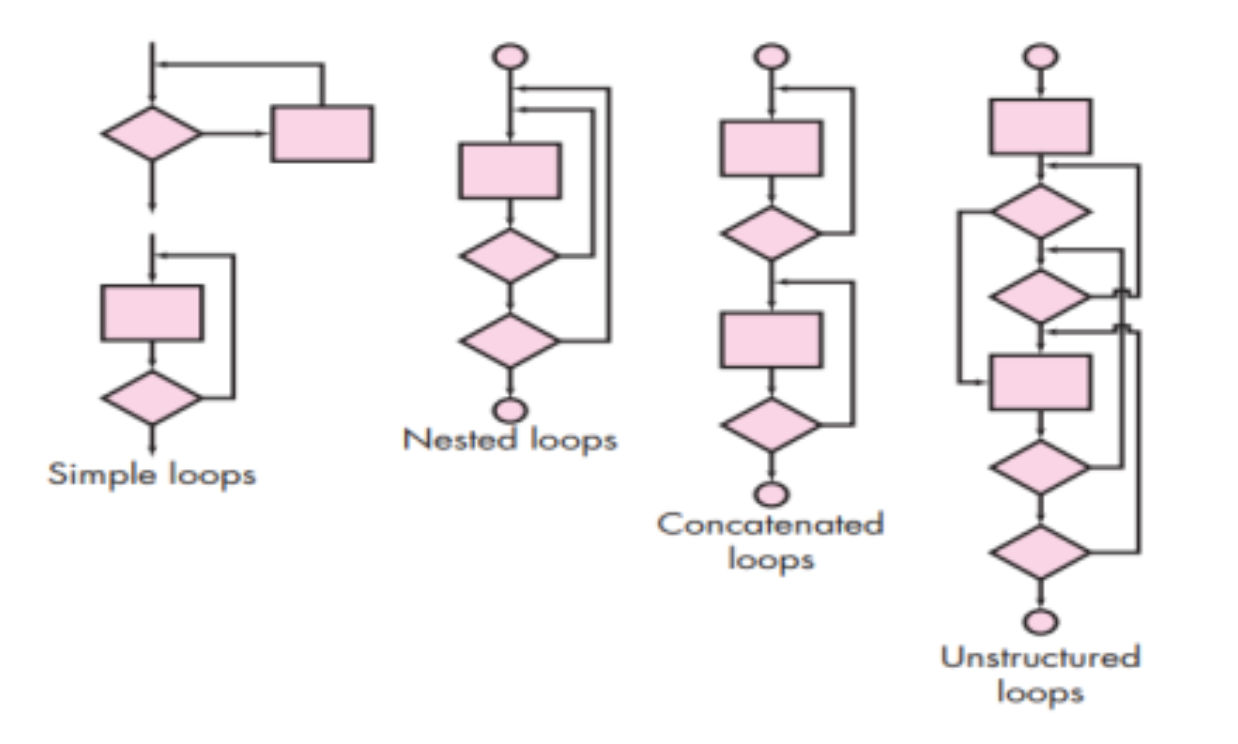
White Box Testing
Also called glass box testing. It uses the control structure to derive test cases. It exercises all independent paths, Involves knowing the internal working of a program, Guarantees that all independent paths will be exercised at least once .Exercises all logical decisions on their true and false sides, Executes all loops,Exercises all data structures for their validity.
Techniques:
- Basic Path Testing
- Control Structure Testing
Basic Path Testing:
 Control Structure Testing:
Types:
Control Structure Testing:
Types:
- Simple Loops
- Nested Loops
- Concatenated Loops
- Unstructured Loops
Art of Debugging
Debugging occurs as a consequence of successful testing. It is an action that results in the removal of errors.
Debugging has two outcomes:
- cause will be found and corrected
- cause will not be found
Characteristics of bugs:
- Symptom and cause can be in different locations
- Symptoms may be caused by human error or timing problems
Strategies:
- Brute Force Method.
- Back Tracking
- Cause Elimination
Quality Concepts
- Quality of Design
- Quality of Conformance
- Quality Control
- Quality Assurance
Software Quality Assurance
Activities:
- Prepare SQA plan for the project.
- Participate in the development of the project’s software process description.
- Review software engineering activities to verify compliance with the defined software process.
- Audit designated software work products to verify compliance with those defined as part of the software process.
- Ensure that any deviations in software or work products are documented and handled according to a documented procedure.
- Record any evidence of noncompliance and reports them to management.
Statistical Quality Assurance
Information about software defects is collected and categorized.
Three core steps:
- Define customer requirements, deliverables, and project goals via well-defined methods of customer communication.
- Measure each existing process and its output to determine current quality performance (e.g., compute defect metrics)
- Analyze defect metrics and determine vital few causes.
ISO 9000 Quality Standards
ISO (International Standards Organization) is a group or consortium of 63 countries established to plan and fosters standardization. ISO declared its 9000 series of standards in 1987. It serves as a reference for the contract between independent parties. The ISO 9000 standard determines the guidelines for maintaining a quality system. The ISO standard mainly addresses operational methods and organizational methods such as responsibilities, reporting, etc. ISO 9000 defines a set of guidelines for the production process and is not directly concerned about the product itself.
Types:
- ISO 9001: This standard applies to the organizations engaged in design, development, production, and servicing of goods. This is the standard that applies to most software development organizations.
- ISO 9002: This standard applies to those organizations which do not design products but are only involved in the production. Examples of these category industries contain steel and car manufacturing industries that buy the product and plants designs from external sources and are engaged in only manufacturing those products. Therefore, ISO 9002 does not apply to software development organizations.
- ISO 9003: This standard applies to organizations that are involved only in the installation and testing of the products. For example, Gas companies.