Unit-1
Physical Layer
Transmission medium
It’s defined as anything that carries information from source to destination Types:
- Guided (Wired)
- Twisted Pair Cable
- Coaxial Cable
- Fibre Optic Cable
- Unguided (Wireless)
- Radio Waves
- Micro Waves
- Infrared
Network Hardware
Repeater: Used to regenerate signal over long distances for good signal strength
HUB: A central device that connects multiple computers on the same network
Bridge: Used to connect two different LANs (Local Area Network)
Switch: Connects devices in a network to each other
Router: Routes the packet from source address to destination address through IP address
OSI (Open System Interconnection)
It’s an abstract model, it consists of 7 layers:
- Application
- Presentation
- Session
- Transport
- Network
- Data Link
- Physical
Physical Layer
Responsible for physical connection between two devices, information is in the form of bits
Functions:
- Bit Synchronization
- Bit Rate Control
- Physical topology: bus, star, mesh, ring
- Transmission Media: simple, half-duplex, full-duplex
Data Link Layer
Responsible to transmit error free data and also reliable and efficient communication. Here data is represented as frames.
Functions:
- Framing
- Error Control
- Flow Control
- Access Control
Network Layer
Responsible for routing the packets from source to destination. Here data is represented as packets.
Functions:
- Logical Addressing
- Fragmentation
Transport Layer
Provides logical communication between the application of different hosts. Gives acknowledgement for successful data transmission. Here data is represented as segments
Functions:
- End-to-End delivery
- Reliable delivery
Session Layer
Responsible for session establishment, maintenance and transmission
Functions:
- Synchronization
Presentation Layer
Specifies how to present the data from source to destination
Functions:
- Translation
- Encryption / Decryption
- Compression
Application Layer
It contains applications itself, which produce data that will be transmitted over the network
Services:
- Email Services
- File transfer
TCP / IP Model
It’s an implementation model, It has 4 layer:
- Application
- Transport
- Network
- Data Link
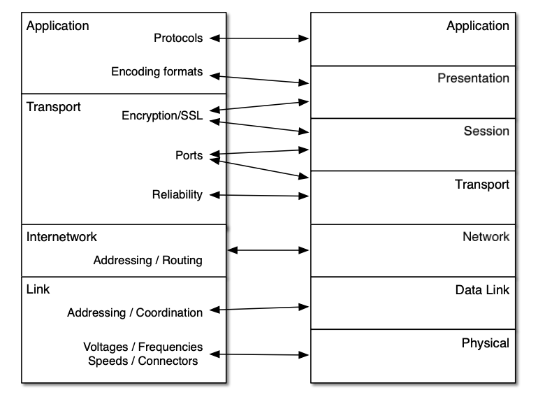
Difference b/w TCP / IP and OSI
| OSI | TCP / IP |
|---|---|
| It’s a reference Model | It’s an implementation Model |
| It consists 7 layers | It consists 4 layers |
| Session and Presentation layer are separated explained | Combines both session and presentation layer |
| Model is designed before the protocol | Protocol is implemented before the model |
| Protocol independent standard | Protocol depended standard |
Unit-2
Data Link Layer
Functions:
- Framing
- Flow control
- Access Control
- Error Control
- Physical addressing
Framing
Link layer moves bits in the form of frames from source to destination. Each frame is distinguishable from one another. Framing adds both the sender and receiver address.
There are two types of framing:
- Fixed size framing
- Variable size framing
Fixed Size Framing
There is no need to define boundaries of the frames, the size the frame itself acts as an delimiter. All the frames will be of the same fixed size.
Variable Size Framing
Here we need to define end of frame and beginning of the next frame.
There are two approaches:
- Character Oriented
- Bit Oriented
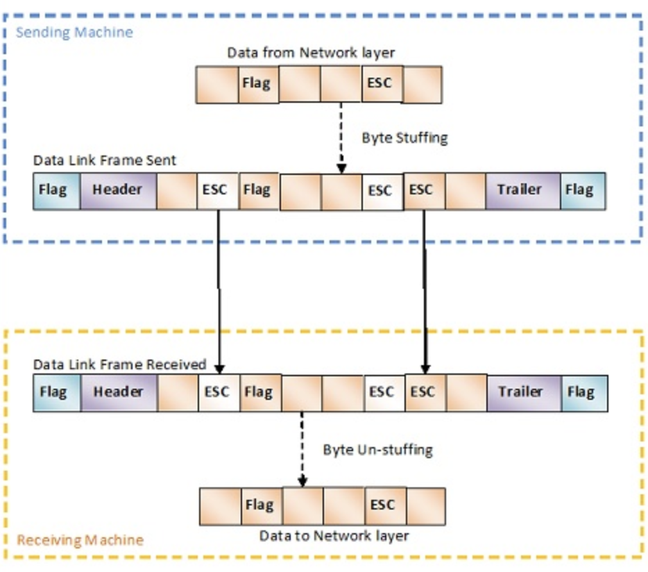
Character Oriented Protocol
A frame contains header, trailer which contains source, destination addresses and error correction. A new 8-bit or 1 byte flag is added to the frame at the beginning and end of the frame.
Character oriented protocol was popular when only text was exchanged through data link layer. Any patter used for the flag could also be part of the text message. If this happens the receiving computer assumes the message is a flag, to avoid this byte stuffing is used.
Byte stuffing
It’s a process of adding an extra byte when ever there is a flag or escape character in the message, which tells to skip that flag or esc character.
Bit Oriented Protocol
We have a delimiter at the beginning and end of the frame. Most protocols use a 8-bit pattern as a flag. Then again that flag could be the actual data so we use bit stuffing to avoid this confusion.
Bit Stuffing
An extra bit “0” is added when the data contains when five consecutive “1”s followed by a “0”.

Error Detection and Correction
Types of errors:
- Single bit error
- Burst error
Error Detection
Two ways:
- Parity check
- Cyclic Redundancy Check
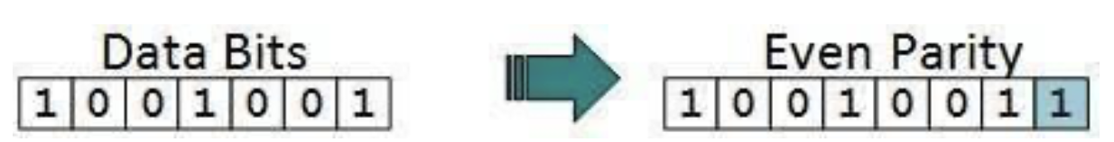
Parity Check
A parity bit is added to the data to check for any error. If it’s a even parity the number of ones in the data should be even, if there are even 1s in data then “0” is added and if there are odd 1s in the data “1” is added. The receiving computer checks the at the number of 1s and decides if there is error or not.
When more than 1 bit is corrupted parity check is useless.
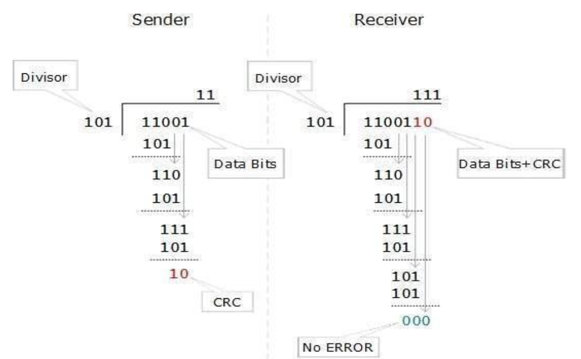
Cyclic Redundancy Check
Here the data is divided by a polynomial and the remainder is added to the data and sent to the receiving computer. The receiving computer then divides that data with the same polynomial, the remainder should be zero if not the data corrupted and there is an error.
Error Correction
Two ways:
- Backward Error Correction: When an error is detected the receiving computer asks to resend the data
- Forward Error Correction: When an error is detected the receiving computer auto corrects the error using error-correcting code.
Backward Error Correction is useful when retransmission is inexpensive like fibre optics.
Elementary Data Link Protocols
Protocols of data link layer enables it to perform it’s basic function: framing, error control, flow control.
Types:
- For Noise-less Channels
- Simplex
- Stop-and-wait
- For Noisy Channels
- Stop-and-wait ARQ
- Go-back-N ARQ
- Selective Repeat ARQ
Simplex
It’s a hypothetical protocol designed for unidirectional data transmission over an ideal channel through which data transmission will can never go wrong. The sender sends all the available data and receiver process all the data at once. Since it’s hypothetical there is no flow control and error control.
Stop-and-Wait
It’s for noise-less channels. It provides unidirectional data transmission without any error-control facilities. However it provides flow-control facilities so that the fast sender does not clog the slow receiver. Sender can only send a frame when it receives the acknowledgement that receiver is available for further data.
Stop-and-Wait ARQ
Stop-and-Wait ARQ (Automatic Repeat Request) is a variation of above protocol but with error control facility appropriate for noisy channels. The sender keeps the copy of the frames and waits for the acknowledgement from the receiver for a certain time, if it doesn’t receive any ack or neg-ack then it retransmits the frame, if positive ack is received it sends the next frame
Go-back-N ARQ
It provides for sending multiple frames before receiving any acknowledgement of first frame. It uses a concept of sliding window so it’s a sliding window protocol. The frames are sequentially numbered and finite number of frames are sent. If ack is not received all the frames are sent again.
Selective Repeat ARQ
Same as Go-back-N ARQ but when if it doesn’t receive ack for frames it only sends those frames for which the ack is not received.
Unit-3
Design Issues
- Store and forward packet switching
- Services provided to Transport layer
- Implementation of connectionless service
- Implementation of connection oriented service
Routing Algorithms
types:
- Non-adaptive
- Shortest Path
- Flooding
- Adaptive
- Distance Vectoring
- Hierarchical Routing
- Link State Routing
Congestion Control
Congestion occurs when there is an overload in the network. When more number of packets are being sent then the network capacity. Congestion Control either prevents this from happening or solves the congestion.
Categories:
- Open Loop Congestion Control
- Retransmission Policy
- Window Policy
- Acknowledgement Policy
- Discarding Policy
- Admission Policy
- Closed Loop Congestion Control
- Back Pressure
- Choke Packet
- Implicit Signaling
- Explicit Signaling
Congestion Control Algorithms:
- Leaky Bucket
- Token Bucket
Quality of Service
Its a internetworking issue which can be defined as a flow which is required for communication.
Flow Characteristics:
- Reliability
- Delay
- Jitter
- Bandwidth
Unit-4
TCP (Transmission Control Protocol)
Responsible for delivery of a message from one process to another. A process is an application program running on a host
Three protocols:
- TCP
- UDP
- SCTP (Stream Control Transmission Protocol)
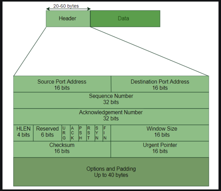
Six flags:
- URG - Urgent Pointer is valid
- FIN - Terminate the connection
- ACK - Acknowledgement is valid
- SYN - Synchronize
- RST - Reset the Connection
- PSH - Request for PUSH
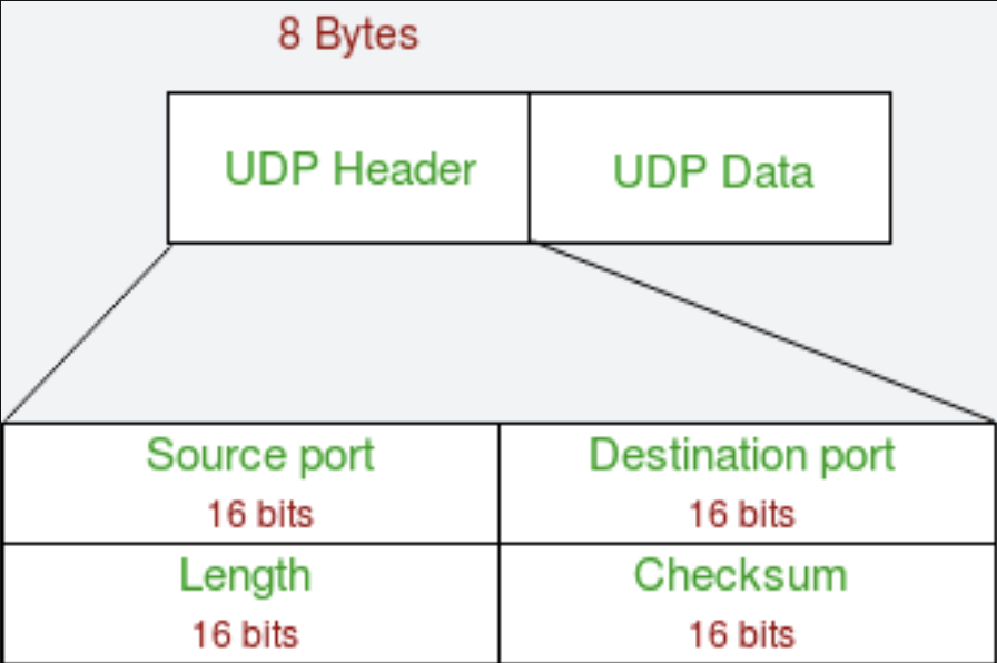
UDP (User Datagram Protocol)
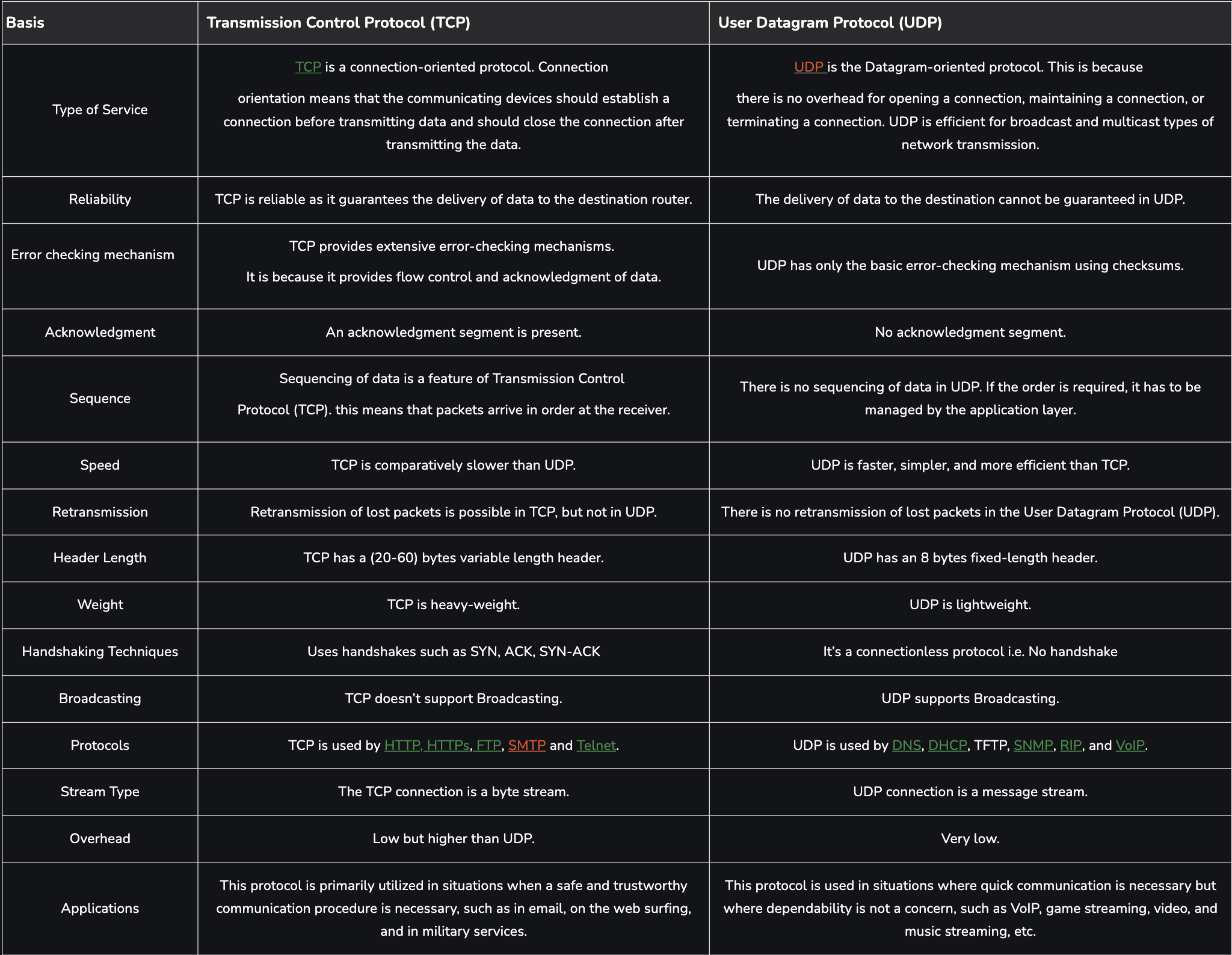
TCP and UDP differences
Unit-5
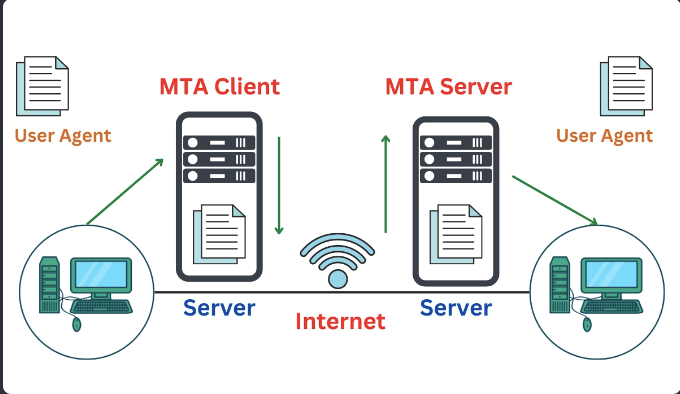
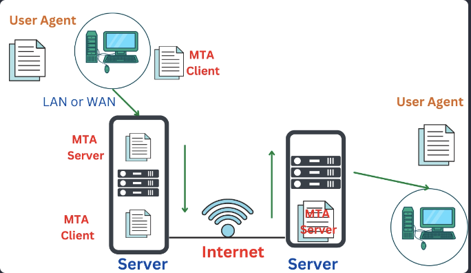
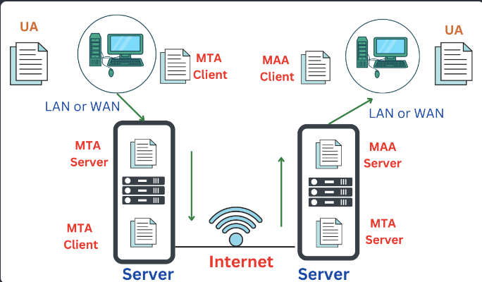
E-mail Architecture
Four Scenarios:
- First Scenario:
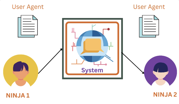
- Second Scenario:
- Third Scenario:
- Fourth Scenario:
DNS (Domain Naming System)
DNS is a directory service that provides a mapping between the name of a host on the network and its numerical address. DNS is a service that translates the domain name into IP addresses. This allows the users of networks to utilize user-friendly names when looking for other hosts instead of remembering the IP addresses.
Three types of Domains:
- Generic
- Country
- Inverse
Generic: .org, .com, .dev and so on
Country: .in, .us, .ca, .uk
Inverse: When the sever wants to know the host of an address to know it’s authorization it request it’s name. This is called inverse domain when we have and address and want to know the name